Basic Electronics and Electrical Engineering: Chapter 4: Synchronous Machines
Synchronous Machines: Important Solved Examples Problems
Anna University Important Solved Examples Problems with Formula, Equation, Explained Solution - Basic Electronics and Electrical Engineering: Chapter 4: Synchronous Machines
SOLVED
EXAMPLES
EXAMPLE 1
A 3‒phase, 50 Hz Star
connected alternator has 150 conductors per phase and flux per pole is 0.05 Wb.
Find (i) emf generated per phase and (ii) Line voltage. Assume the winding to
be full pitched and distribution factor to be 0.96.
Given
Data:
z = 150 conductors, ϕ =
0.05 Wb, f = 50 Hz
To
find: (i) EMF generated per phase, (ii) Line voltage
Solution
(i) EMF generated per
phase
Eph
= 2.22 KpKdfϕz
For full pitch coil,
Kp = 1
Kd = 0.96
Eph = 2.22 KpKdfϕz
Eph = 2.22 ×
1 × 0.96 × 50 × 0.05 × 150
Eph
= 799.2 Volts
(ii) Line voltage
In a star connected
system,
EL = √3 Eph
= √3 × 799.2
EL=1384.214
Volts
EXAMPLE 2
Find the flux per pole
of a 3‒phase, 50 Hz, 10‒pole alternator. The number of armature conductors in
series per phase is 372. The winding is star connected to give a line voltage
of 10 kV. Assume Kp=1 and Kd=0.96.
Given
Data:
f
= 50 Hz, p = 10, Z=372 conductors, Kp = 1, Kd=0,96,
Erms/phase =
2.22 KpKdfϕz,
Flux per
pole, ϕ = Erms/phase / 2.22 KpKdfz
To
find: Generated emf/phase.
Solution
Generated emf/phase,
Erms/ph = EL
/ √3
= 10000 / √3
= 5773.5 volts
ϕ = 5773.5 / (2.22 × 1
× 0.96 × 50 × 372)
ϕ = 0.1456 Wb
EXAMPLE 3
The armature of an 8‒pole,
3‒phase, 50 Hz alternator has 18 slots and 10 conductors/slot. A flux of 0.05
Wb is entering the armature from one pole to other. Calculate the induced emf
per phase.
Given
Data: p=8, f =
50 Hz, No. of slots = 18, No. of conductors/slots = 10
To
find: Induced emf per phase
Solution
∴
Total no. of conductors = No. of conductors/slot × No. of slots
= 10 × 18
= 180 conductors
No. of conductors/phase
= 180 / 3 = 60 conductors/phase
Flux, ϕ = 0.05 Wb
Induced emf per phase Eph
= 2.22 KpKdfϕz
= 2.22 × 1× 1 × 50 ×
0.05 × 60
Eph=333
volts
EXAMPLE 4
A 3‒phase star‒connected,
50 Hz alternator has 96 conductors per phase and a flux/pole 0.1 Wb. The
alternator winding has a synchronous reactance of 5Ω/phase and negligible resistance.
The distribution factor for the stator winding is 0.96. Calculate the terminal
voltage when three non‒inductive resistance of 10Ω/phase, are connected in star
connection across the terminals.
Given
Data: Z= 96 conductors, ϕ = 0.1 Wb, f = 50 Hz, XS = 50Ω/phase, Kd=0.96, Ra
= 10Ω/phase
To
find: Terminal voltage
Solution
Assume that, Kp
= 1
Generated emf/phase, E =
2.22 KpKdZfϕ
= 2.22 × 1 × 0.96 × 96 ×
50 × 0.1
E = 1023 V
Impedance / phase, Z=√
[Ra2+XS2]
=√ [(10)2+(5)2]
Z = 11.18 Ω
Current / phase, Ia
= E/Z
= 1023 / 11.18
Ia = 91.5 A
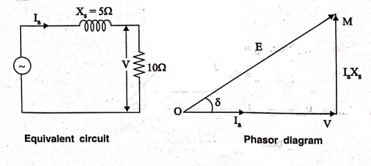
The above fig. shows
the equivalent circuit for one phase of the alternator while the other figure
shows its phasor diagram.
Terminal voltage/phase,
V = √ [ E2 + (IaXS)2 ]
V= √[(1023)2
‒ (91.5×5)2]
V=915 V
In a star connected
system,
Terminal line voltage VL
=√3V
VL =√3×915
VL = 1585 V
EXAMPLE 5
A 1500 kVA, 6.6 kV, 3‒phase,
star ‒ connected alternator has a resistance of 0.50Ω/phase and a synchronous
reactance of 50Ω/phase. Find its voltage regulation for (i) Unity p.f (ii) 0.8 lagging p.f and (iii) 0.8 leading p.f.
Given
Data: P=1500 kVA, VL = 6.6 kV = 6600 kV, Ra
= 0.5Ω/phase, XS = 50Ω/phase
To
find: Line current, Armature current/phase, Voltage phase
Solution
Line current, IL
= P / √3VL
= 1500×103 /
√3×6600
IL=131
A
Armature current/phase,
Ia = IL = 131 A
VL = √3 Vph
Voltage/phase, Vph
= VL / √3
= 6600 / √3
= 3810 V
IaRa
= 131 × 0.5 = 65.5 V
IaXS
= 131×5=655 V
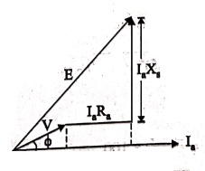
(i) Unity p.f
For Unity p.f (Ref
Fig.).
E = √[ (V+IaRa)2
+ (IaXS)2 ]
= √[(3810+65.5)2
+ (655)2]
E = 3930 V
% Regulation = [(E‒V)/V]
× 100
= (3930‒3810)/3810 ×
100
% Regulation = 3.15%
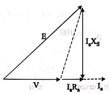
(ii) 0.8 lagging p.f
For lagging p.f (Ref
Fig.) current has been taken as the reference phasor.
cos ϕ = 0.8
sin ϕ = 0.6
E = √[ ( Vcosϕ + IaRa)2
+ (Vsinϕ + IaXS)2 ]
= √[ (3810×0.8 + 65.5)2
+ (3810×0.6 + 655)2]
= 4283 V
% Regulation = [(E‒V)/V]
× 100
= (4283‒3810)/3810 ×
100
= 12.4%
(iii) 0.8 p.f leading
For leading p.f (Ref Fig.), current has been taken
as reference phasor.
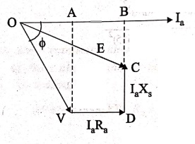
E = √[(OB)2
+ (BC)2]
OB = OA + AB
= Vcosϕ + IaRa
BC = BD‒CD
= V sinϕ ‒ IaXs
E = √[ ( Vcosϕ + IaRa)2
+ (Vsinϕ ‒ IaXS)2 ]
= [(3810×0.8 + 65.5)2
+ (3810×0.6 − 655)2]
= 3515 V
% Regulation = [(E‒V)/V]
× 100
= (3515‒3810)/3810 ×
100 = ‒7.7%
EXAMPLE 6
A 500 kVA, 3.3 kV, 3
phase, star connected alternator is found to give a short circuit current of
290 A at normal field current. Its effective winding resistance per phase is
0.7Ω. Estimate the full load voltage regulation for (i) 0.8 p.f lagging and
(ii) UPF.
Given
data: Power = 500 kVA, V = 3.3 kV, short circuit current,
I = 290 A, R= 0.7Ω
Solution
Vph = 3.3×10³
/ √3
= 1905.25 V
Z2 = Vph
/ I
= 1905.25 / 290
= 6.57 Ω
XS = √[ZS2‒Ra2]
= √[6.572 ‒0.72]
XS = 6.57 Ω
IFL = (500×103)
/ (3×1905.25)
IFL = 87.47
A
0.8 p.f lagging
E = √[ ( Vcosϕ + IaRa)2
+ (Vsinϕ + IaXS)2 ]
= √ [ (1905.25×0.8 +
87.47×0.7)2 + (1905.25×0.6 + 87.47×6.57)2 ]
= 2334.99 V
% Regulation = [(E0‒V)/V]
× 100
= ( 2334.99‒1905.25 / 1905.25)
× 100
%
Regulation = 22.55%
(ii) Unity power
factor'
E0 = √[ (V+IaRa)2
+ (IaXS)2 ]
= √[ (1905.25+87.47 ×
0.7)2 + (87.47 × 6.57)2 ]
E0 = 2047.8
% Regulation = [(E0‒V)/V]
× 100
= ( 2047.8‒1905.25 / 1905.25
) × 100
%
Regulation=7.48%
EXAMPLE 7
A 600 V, 600 KVA
single phase alternator has Ra=0.3 Ohm. An exciting current of 5A
produces an emf of 400 V, On open circuit and an armature current of 200 A on
short circuit. Calculate: 1. Synchronous impedance and reactance, 2. The full
load regulation with 0.8 p.f lagging
Given
Data: The phase voltage V = 600 V; Capacity = 600 kVA;, Ra
= 0.3 Ω, Exciting Current = 5 A, Open Circuit voltage Voc= 400 V, Short circuit
current Isc=200 A
To
find: 1. Zs, Xs, 2. % R (at 0.8 p.f lag)
Solution
1. Zs, Xs
Voc=400 V for If=5 A
Isc=200 A for If=5 A
Zs = (Voc/Isc)|Same
If
Zs = 400/200 = 2Ω
Now, Zs=√[Ra2+XS2]
Zs = √(0.3)2
+XS2]
4 = (0.3)2 +
XS2
XS2=4-0.09
Xs=1.97≈
20Ω
2. For lagging pf load
(% R at 0.8 P.flag)
Eph2
= (Vcosϕ +IaRa)2 + (Vsinϕ + IaXa)2
= (600×0.8 + (200)(0.3))2
+ (600×0.6 + (200) (2))2
E2ph
= 869200
Eph = 932.309
V
% Reg = [ ( Eph
‒ Vph ) / Vph ] × 100
= [ (932.309 – 600) / 600
] × 100
% Reg=55.4%
EXAMPLE 8
From the following
test results, determine the voltage regulation of a 2000 V single phase
alternator delivering a load current of 100 A at 0.8 lagging pf.
Test results: An
excitation of 2.5 A produces a current of 100 A in the stator winding on short
circuit and an emf of 500 V on open circuit. Assume an effective resistance of
0.8.2Ω
Given
Data: The phase voltage Vph = 2000 V, Ra=0.8Ω, Load
Current IL= 100 A, Isc=100 A for If=2.5 A, Voc=500 V for If=2.5 A
To
find: % Regulation (at 0.8 p.f lag)
SOLUTION
Zs = (Voc/Isc)|Same
If
Zs = 500/100 = 5Ω
Now, Zs=√[Ra2+XS2]
5 = √(0.8)2
+XS2]
XS2=25-0.64
XS = 4.93 Ω ‒
5Ω
For lagging pf load,
Eph2
= (Vcosϕ +IaRa)2 + (Vsinϕ + IaXs)2
= (2000×0.8 + (100)
(0.8))2 + (2000×0.6 + (100) (5))2
E2ph
= 5712400
Eph =
2390.06 V.
% Reg = [ ( Eph
‒ Vph ) / Vph ] × 100
= [ (2390.06‒2000) / 2000
] × 100
%
Reg=19.5%
Basic Electronics and Electrical Engineering: Chapter 4: Synchronous Machines : Tag: Basic Engineering : - Synchronous Machines: Important Solved Examples Problems
Basic Electronics and Electrical Engineering: Chapter 4: Synchronous Machines
Under Subject

Basic Electronics and Electrical Engineering
EE25C04 1st Semester ECE Dept | 2025 Regulation | 2nd Semester 2025 Regulation
Related Subjects

English Essentials I
EN25C01 1st Semester | 2025 Regulation | 1st Semester 2025 Regulation

தமிழர் மரபு - Heritage of Tamils
UC25H01 1st Semester | 2025 Regulation | 1st Semester 2025 Regulation

Applied Calculus
MA25C01 Maths 1 M1 - 1st Semester | 2025 Regulation | 1st Semester 2025 Regulation

Applied Physics I
PH25C01 1st Semester | 2025 Regulation | 1st Semester 2025 Regulation

Applied Chemistry I
CY25C01 1st Semester | 2025 Regulation | 1st Semester 2025 Regulation

Makerspace
ME25C04 1st Semester | 2025 Regulation | 1st Semester 2025 Regulation

Computer Programming C
CS25C01 1st Semester | 2025 Regulation | 1st Semester 2025 Regulation

Computer Programming Python
CS25C02 1st Semester | 2025 Regulation | 1st Semester 2025 Regulation

Fundamentals of Electrical and Electronics Engineering
EE25C03 1st Semester | 2025 Regulation | 1st Semester 2025 Regulation

Introduction to Mechanical Engineering
ME25C03 1st Semester | 2025 Regulation | 1st Semester 2025 Regulation

Introduction to Civil Engineering
CE25C01 1st Semester Civil Department | 2025 Regulation | 1st Semester 2025 Regulation

Essentials of Computing
CS25C03 1st Semester - AID CSE IT Department | 2025 Regulation | 1st Semester 2025 Regulation

Applied Physics I Laboratory
PH25C01 1st Semester practical Laboratory Manual | 2025 Regulation | 1st Semester Laboratory 2025 Regulation

Applied Chemistry I Laboratory
CY25C01 1st Semester practical Laboratory Manual | 2025 Regulation | 1st Semester Laboratory 2025 Regulation

Computer Programming C Laboratory
CS25C01 1st Semester practical Laboratory Manual | 2025 Regulation | 1st Semester Laboratory 2025 Regulation

Computer Programming Python Laboratory
CS25C02 1st Semester practical Laboratory Manual | 2025 Regulation | 1st Semester Laboratory 2025 Regulation

Engineering Drawing
ME25C01 EEE Mech Dept | 2025 Regulation | 2nd Semester 2025 Regulation
Basic Electronics and Electrical Engineering
EE25C04 1st Semester ECE Dept | 2025 Regulation | 2nd Semester 2025 Regulation