Basic Electronics and Electrical Engineering: Chapter 4: Synchronous Machines
Synchronous Motor
Characteristics, Construction, Principle of Operation, Equivalent Circuit, Applications, Comparison
1. Characteristics of Synchronous Motor 2. Construction of Synchronous Motor. 3. Principle of Operation of Synchronous Motor. 4. Making Synchronous Motor Self Starting. 5. Equivalent Circuit of Synchronous Motor 6. Synchronous Capacitor. 7. Applications of Synchronous Motor 8. Comparison between Synchronous Motor and Induction Motor
SYNCHRONOUS
MOTOR
Basically a DC
generator can be run as a d.c motor. Similarly, an alternator may operate as a
motor connecting its armature winding to a 3 phase supply. It is then called a
synchronous motor.
Characteristics of Synchronous Motor
Some characteristic
features of a synchronous motors are given below:
1. It runs either at
synchronous speed or not at all i.e., while running, it maintains a constant
speed.
2. It is not inherently
self starting. It has to be run upto synchronous speed by some means before it
can be synchronised to supply.
3. It is capable of
being operated under a wide range of power factors both lagging and leading.
Hence, it can be used for power correction purpose in addition to supplying
torque to drive loads.
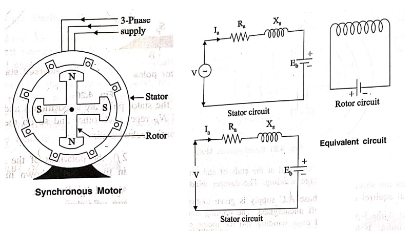
Construction of Synchronous Motor
A synchronous motor is
a machine that operates at synchronous speed and converts electrical energy
into mechanical energy. A synchronous motor has the following two parts.
1. Stator
A stator which houses 3
phase armature winding in the slots of the laminated stator core and receives
power from a 3‒phase supply. This construction is similar to those of a 3 phase
squirrel cage or a wound rotor induction motor.
2. Rotor
The rotor is generally
a salient pole rotor. The number of rotor field poles must equal the number of
stator poles. In order to eliminate hunting and to develop the necessary
starting torque when A.C voltage is applied to the stator. The rotor poles
contain pole‒face conductors which are short‒circuited at their ends. The
salient pole rotor excited by direct current to form alternate N and S poles.
The exciting coils are connected in series to two slip rings exciter mounted r
mounted on the rotor shaft.
Principle of Operation of Synchronous Motor
The fact that a
synchronous motor has no starting torque can be easily explained.
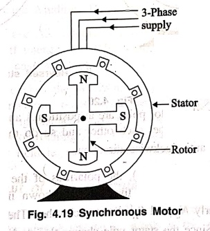
Consider a 3‒phase
synchronous motor having two rotor poles NR and SR. Then
the stator also having two poles NS and SS. The motor has
direct voltage applied to the rotor winding and a 3‒phase ac voltage applied to
the stator winding. The stator winding produces a rotating magnetic field which
revolves round the stator at synchronous speed NS. The direct
current is applied to a two pole field which is stationary so long as the rotor
is not running. Thus we have a situation in which there exists a pair of
revolving armature poles. (ie, NS→SS) and a pair of
stationary rotor poles (ie, NR→SR)

Suppose at any instant,
the stator poles are at position A and B as shown in Fig. 4.20 (a). It is clear
that poles NS and NR repel each other and so do the poles
SS and NS. Therefore the rotor tends to move in anti‒clockwise
direction.
After a period of half‒cycle
(1/2 f), the polarities of the stator
poles are reversed but the polarities of the rotor poles remain the same as
shown in Fig. 4.20 (b). Now SS and NR attract each other
similarly NS and SR attract each other. Therefore, the
rotor tends to move in the clock‒wise direction. Since the stator pole change
their polarities rapidly, they tend to pull the rotor first in one direction
and then after a period of half cycle in the other. Due to high inertia of the
rotor, the motor fails to start.
Hence, a synchronous
motor has no self‒starting torque ie, a synchronous motor cannot start by
itself.
Making Synchronous Motor Self Starting
1.
Using the damper windings as a squirrel cage induction motor
(i) A synchronous motor
cannot start by itself. In order to make the motor self starting, a squirrel
cage winding (also called damper winding) is provided on the rotor. The damper
winding consists of copper bars embedded on the pole faces of the salient poles
of the rotor as shown in Fig. 4.21.

The bars are short
circuited at the ends of end ring arrangement to form in effect a partial
squirrel cage winding. The damper winding serves to start the motor.
(ii) To start with, 3‒phase
A.C supply is given to the stator winding while the rotor field winding is left
unenergised. The rotating stator field induces currents in the damper or
squirrel cage winding and the motor starts as a induction motor.
(iii) As the motor approaches
the synchronous speed, the rotor is excited with direct current. Now the
resulting poles on the rotor face poles of opposite polarity on the stator and
a strong magnetic attraction is set up between them. The rotor poles lock with
the poles of rotating flux. Consequently, the rotor revolves at the same speed
as the stator field ie, at synchronous speed.
Equivalent Circuit of Synchronous Motor
Basically, the
synchronous motor is connected to two electrical supply; a DC supply at the
rotor terminals for excitation purpose and an ac supply at the stator
terminals.
1. Under normal
conditions, no voltage is induced in the rotor terminals by the stator field
because the rotor winding is rotating at the same speed as the stator field.
2. In the stator winding,
two effects are to be considered.
(i) The effect of
stator field on the stator conductors is accounted for by including an
inductive reactance in the armature winding. This is called synchronous
reactance XS. A resistance Ra is connected in series with
synchronous reactance to account for the copper losses in the stator or
armature winding.
(ii) The second effect
is that a voltage is generated in the stator. winding by the synchronously
revolving field of the rotor. This generated emf Eb is known as back
emf. It opposes the stator voltage 'V'. The magnitude of EMF Eb
depends upon the rotor speed and rotor flux ϕ per pole. The equivalent circuit
of synchronous motor as shown in Fig. 4.22 and 4.23.

Synchronous Capacitors
An over excited
synchronous motor running on no load is called as synchronous capacitor.
We have seen that, a
synchronous motor takes a leading current when over excited and, therefore,
behaves as capacitor. When a synchronous machines is connected in parallel with
any induction motors that operate at lagging powerfactor, the leading KVAR
supplied by the synchronous capacitor reduces the lagging reactive KVAR of the
loads. Consequently, powerfactor of the entire system is improved.
Applications of Synchronous Motor
1. Over excited
synchronous motors can be used to improve the powerfactor of a plant and other
devices having lagging p.f such as welders and fluorescent lights etc.,
2. Low speed
synchronous motors are used for drives such as centrifugal and screw‒type
pumps, ball and tube mills, vaccum pumps, chippers and metal rolling mills
etc.,
3. They are used to
improve the voltage regulation of transmission lines.
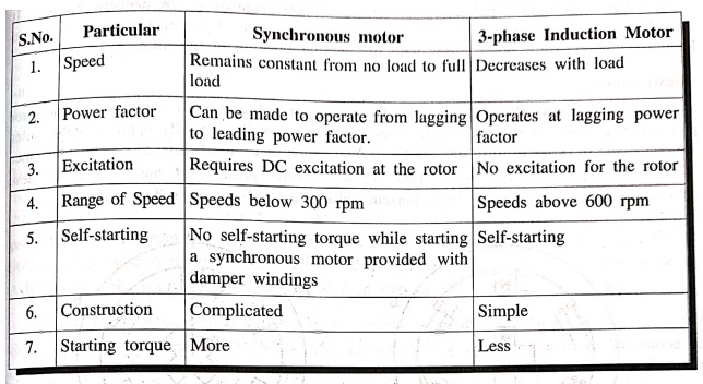
Comparison between Synchronous Motor and Induction Motor
Basic Electronics and Electrical Engineering: Chapter 4: Synchronous Machines : Tag: Basic Engineering : Characteristics, Construction, Principle of Operation, Equivalent Circuit, Applications, Comparison - Synchronous Motor
Basic Electronics and Electrical Engineering: Chapter 4: Synchronous Machines
Under Subject

Basic Electronics and Electrical Engineering
EE25C04 1st Semester ECE Dept | 2025 Regulation | 2nd Semester 2025 Regulation
Related Subjects

English Essentials I
EN25C01 1st Semester | 2025 Regulation | 1st Semester 2025 Regulation

தமிழர் மரபு - Heritage of Tamils
UC25H01 1st Semester | 2025 Regulation | 1st Semester 2025 Regulation

Applied Calculus
MA25C01 Maths 1 M1 - 1st Semester | 2025 Regulation | 1st Semester 2025 Regulation

Applied Physics I
PH25C01 1st Semester | 2025 Regulation | 1st Semester 2025 Regulation

Applied Chemistry I
CY25C01 1st Semester | 2025 Regulation | 1st Semester 2025 Regulation

Makerspace
ME25C04 1st Semester | 2025 Regulation | 1st Semester 2025 Regulation

Computer Programming C
CS25C01 1st Semester | 2025 Regulation | 1st Semester 2025 Regulation

Computer Programming Python
CS25C02 1st Semester | 2025 Regulation | 1st Semester 2025 Regulation

Fundamentals of Electrical and Electronics Engineering
EE25C03 1st Semester | 2025 Regulation | 1st Semester 2025 Regulation

Introduction to Mechanical Engineering
ME25C03 1st Semester | 2025 Regulation | 1st Semester 2025 Regulation

Introduction to Civil Engineering
CE25C01 1st Semester Civil Department | 2025 Regulation | 1st Semester 2025 Regulation

Essentials of Computing
CS25C03 1st Semester - AID CSE IT Department | 2025 Regulation | 1st Semester 2025 Regulation

Applied Physics I Laboratory
PH25C01 1st Semester practical Laboratory Manual | 2025 Regulation | 1st Semester Laboratory 2025 Regulation

Applied Chemistry I Laboratory
CY25C01 1st Semester practical Laboratory Manual | 2025 Regulation | 1st Semester Laboratory 2025 Regulation

Computer Programming C Laboratory
CS25C01 1st Semester practical Laboratory Manual | 2025 Regulation | 1st Semester Laboratory 2025 Regulation

Computer Programming Python Laboratory
CS25C02 1st Semester practical Laboratory Manual | 2025 Regulation | 1st Semester Laboratory 2025 Regulation

Engineering Drawing
ME25C01 EEE Mech Dept | 2025 Regulation | 2nd Semester 2025 Regulation
Basic Electronics and Electrical Engineering
EE25C04 1st Semester ECE Dept | 2025 Regulation | 2nd Semester 2025 Regulation