Basic Electronics and Electrical Engineering: Chapter 4: Synchronous Machines
Stepper Motor and its Types
These motors, also called stepping motors or step motors, because they rotate through a fixed angular step in response to each input current pulse from its controller.
STEPPER
MOTOR
These motors, also
called stepping motors or step motors, because they rotate through a fixed
angular step in response to each input current pulse from its controller. The
stepper motors are able to provide very precise position and (or speed control)
without needing any feedback loop.
A stepper motor has
salient poles with field coils. The rotor is usually salient pole but has no
exciting coil. The unique feature of a stepper motor is that its shaft rotates
is a series of discrete steps in response to command pulses received from an
electronic control circuit. The only moving port in a stepper motor is its
rotor which has no winding. Hence, it needs no commutator and brushes. This
feature makes the stepper motor quite robust and reliable.
Types of Stepper
Motor
Based on their
construction and working, the stepper motors can be divided into the following
three basic categories.
1. Variable reluctance
(VR) stepper motors
2. Permanent magnet (Pm)
stepper motors
3. Hybrid stepper
motors.
1. Variable reluctance (V) stepper motor
It has wound stator
poles but the rotor poles are made of a ferromagnetic material. It is known as
variable reluctance motor because the reluctance of the magnetic circuit formed
by the stator and rotor poles varies with the angular position of the rotor.
Construction
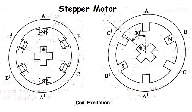
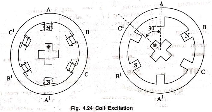
Fig. 4.24 shows the
stepper motor has six stator poles and four rotor poles. The rotor pole width
is same as the stator pole width. The coils on diametrically opposite stator
pole are connected in series to form one circuit or phase such that on emerging
it, one pole become N‒ pole and the other one is S‒ pole. There are three phases
A, B and C. Each of these phases can be energized by a direct current pulse
from a drive controller circuit.
A simple full step
operation of a VR stepper motor is shown in Fig. 4.25. When none of the coils
is energised, the rotor is completely free to rotate. On energizing one or more
coils, the rotor assumes a position thats forms a path of least reluctance with
the magnetized stator poles.
Operations
The operation of one
phase on mode, full step operation VR stepper motor is explained below.
The switch S1
has been closed for energise the phase A. The nearest rotor poles are attracted
by N and S poles of the stator so that the rotor takes the position as shown in
Fig. 4.24. Let us mark by a star symbol the rotor pole just under the N‒ pole
of the stator.
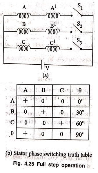
Now let us open the
switch S1 and close the switch S2 to energies the next
phase B. The rotor poles of unmarked pair are now nearest to the new position
of alignment. Therefore the rotor rotates by 30° anticlockwise to align along
the path of least reluctance. Again open the switch S2 and close
switch S3 to energies the phase C. Once again, the nearest rotor
poles to align are from the marked pair. These poles align themselves by
rotating a further 30° anticlock wise direction. This process will be repeated
by excitry the coil in sequence A‒B‒C‒A‒B..., the rotor rotates anticlock wise
in step of 30°.
Now, if the phases are
energised in the reverse sequence, A‒C‒B‒A‒C..., the rotor will rotate
clockwise in steps of 30°. Since only one phase is energised at a time, this
mode of operation is called one‒phase ON operation. The stator phase switching
truth table for this operation is given in Fig. 4.25(b).
Basic Electronics and Electrical Engineering: Chapter 4: Synchronous Machines : Tag: Basic Engineering : - Stepper Motor and its Types
Basic Electronics and Electrical Engineering: Chapter 4: Synchronous Machines
Under Subject

Basic Electronics and Electrical Engineering
EE25C04 1st Semester ECE Dept | 2025 Regulation | 2nd Semester 2025 Regulation
Related Subjects

English Essentials I
EN25C01 1st Semester | 2025 Regulation | 1st Semester 2025 Regulation

தமிழர் மரபு - Heritage of Tamils
UC25H01 1st Semester | 2025 Regulation | 1st Semester 2025 Regulation
Applied Calculus
MA25C01 Maths 1 M1 - 1st Semester | 2025 Regulation | 1st Semester 2025 Regulation
Applied Physics I
PH25C01 1st Semester | 2025 Regulation | 1st Semester 2025 Regulation

Applied Chemistry I
CY25C01 1st Semester | 2025 Regulation | 1st Semester 2025 Regulation
Makerspace
ME25C04 1st Semester | 2025 Regulation | 1st Semester 2025 Regulation
Computer Programming C
CS25C01 1st Semester | 2025 Regulation | 1st Semester 2025 Regulation
Computer Programming Python
CS25C02 1st Semester | 2025 Regulation | 1st Semester 2025 Regulation
Fundamentals of Electrical and Electronics Engineering
EE25C03 1st Semester | 2025 Regulation | 1st Semester 2025 Regulation
Introduction to Mechanical Engineering
ME25C03 1st Semester | 2025 Regulation | 1st Semester 2025 Regulation

Introduction to Civil Engineering
CE25C01 1st Semester Civil Department | 2025 Regulation | 1st Semester 2025 Regulation
Essentials of Computing
CS25C03 1st Semester - AID CSE IT Department | 2025 Regulation | 1st Semester 2025 Regulation

Applied Physics I Laboratory
PH25C01 1st Semester practical Laboratory Manual | 2025 Regulation | 1st Semester Laboratory 2025 Regulation

Applied Chemistry I Laboratory
CY25C01 1st Semester practical Laboratory Manual | 2025 Regulation | 1st Semester Laboratory 2025 Regulation

Computer Programming C Laboratory
CS25C01 1st Semester practical Laboratory Manual | 2025 Regulation | 1st Semester Laboratory 2025 Regulation

Computer Programming Python Laboratory
CS25C02 1st Semester practical Laboratory Manual | 2025 Regulation | 1st Semester Laboratory 2025 Regulation
Engineering Drawing
ME25C01 EEE Mech Dept | 2025 Regulation | 2nd Semester 2025 Regulation
Basic Electronics and Electrical Engineering
EE25C04 1st Semester ECE Dept | 2025 Regulation | 2nd Semester 2025 Regulation