Electron Devices: Chapter 6: Thyristors UJT and Optoelectronic Devices
Diac
Construction, Working Principle, Operation, Symbol, Equivalent Circuit, Characteristics, Applications

Questions: 1. Explain the basic construction of a diac. 2. Explain the working principle of diac. 3. Explain the four transistor analogy for a diac. 4. Draw and explain the characteristics of diac. Explain its operation. 5. Explain the working and characteristics of DIAC and its applications.
Diac
•
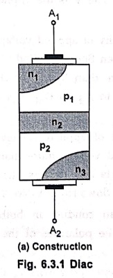
The diac is a two terminal, four layer device. It conducts in either directions
hence it is also called bilateral trigger diode.
•
It has a pair of four layer diodes a shown in Fig. 6.3.1 (a). The two different
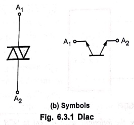
symbols used for the diac are shown in Fig. 6.3.1(b).
•
The terminals of the diac are not named as it can be used in any direction. It
is low power triggering device.
•
There is no control terminal on the diac.
1. Basic Operation
•
The diac can be treated as parallel inverse combination of the semiconductor
layers that permits triggering in either direction.
•
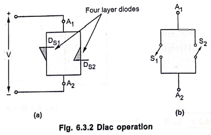
Fig. 6.3.2 (a) shows the diac equivalent circuit as two parallel Shockley
diodes, connected in opposite directions. The Shockley diode is basically a
four layer pnpn diode, with only two external terminals. The characteristics of
Shockley diode are similar to SCR with IG=0. It acts as a switch
which is ON in one direction and OFF in the other.
•
Both the Shockley diodes act as a switch as shown. in Fig. 6.3.2(b). The V is
the applied voltage across A1 and A2.
•
When the polarity of applied voltage is as shown in Fig. 6.3.2 (a) then
Shockley diode DS1 becomes ON when V is more than VBR (F)
of DS1. Thus current flows from A1 to A2 as DS1
acts as closed switch S1.
•
If the polarities of applied voltage V are reversed then for applied voltage
more than VBR (F) of DS2, the DS2 conducts and
its acts like a closed switch S2. The current flows from A2
to A1.
• Thus device can conduct in both the directions, depending on the polarities of the applied voltage across it.
2. Four Transistors Analogy
•
The diac operation can be explained using four transistors analogy.
•
Each pair of transistors form a Shockley diode. The four transistors analogy
and the biasing conditions shown in Fig. 6.3.3 (a) and (b) also can be used to
explain the basic operation of diac.
•
The transistors Q1, Q2 form a Shockley diode DS1
while the transistors Q3, Q4 form a Shockley diode DS2.
The basic operation remains same as explained earlier.
3. Characteristics of Diac
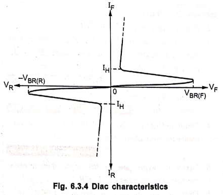
• The diac characteristics are shown in Fig. 6.3.4.
•
As long as the forward voltage is less than the breakdown voltage, the diac is
OFF and the current is small.
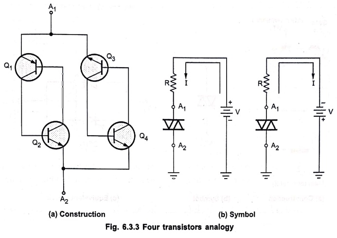
Fig. 6.3.3 Four transistors analogy
•
When the applied forward voltage becomes more than VBR (F) then diac
becomes ON and conducts so that large current flows through it.
•
The diac remains ON as long as the current through it is greater than the
holding current.
•
The diac characteristics are exactly similar in both the directions. But they
are shown in the 1st quadrant and in the 3rd quadrant due to opposite
polarities of voltage and current in the two directions.
4. Applications
The
diac is not a control device, it is used as a triggering device.
•
It is used in,
1.
Triggering of triac
2.
Motor speed control
3.
Temperature control
4.
Light dimming circuits.
Review
Questions
1. Explain the basic construction of a diac.
2. Explain the working principle of diac.
3. Explain the four transistor analogy for a diac.
4. Draw and explain the characteristics of diac. Explain its
operation.
5. Explain the working and characteristics of DIAC and its applications.
Electron Devices: Chapter 6: Thyristors UJT and Optoelectronic Devices : Tag: electronics : Construction, Working Principle, Operation, Symbol, Equivalent Circuit, Characteristics, Applications - Diac
Electron Devices: Chapter 6: Thyristors UJT and Optoelectronic Devices
Under Subject

Electron Devices
EC25C01 2nd Semester ECE Dept | 2025 Regulation | 2nd Semester 2025 Regulation
Related Subjects

English Essentials II
EN25C02 2nd Semester | 2025 Regulation | 2nd Semester 2025 Regulation

Tamils and Technology தமிழர்களும் தொழில்நுட்பமும்
UC25H02 2nd Semester | 2025 Regulation | 2nd Semester 2025 Regulation

Linear Algebra
MA25C02 2nd Semester | 2025 Regulation
Electron Devices
EC25C01 2nd Semester ECE Dept | 2025 Regulation | 2nd Semester 2025 Regulation

Data Structures using CPlusPlus
CS25C05 2nd Semester ECE Dept | 2025 Regulation | 2nd Semester 2025 Regulation

Circuits and Network Analysis
EC25C02 2nd Semester ECE Dept | 2025 Regulation | 2nd Semester 2025 Regulation

Re-Engineering for Innovation
ME25C05 2nd Semester | 2025 Regulation | 2nd Semester 2025 Regulation

Engineering Drawing - Laboratory
ME25C01 2nd Semester | 2025 Regulation | 2nd Semester 2025 Regulation

Data Structures using CPlusPlus - Laboratory
CS25C05 2nd Semester ECE Dept | 2025 Regulation | 2nd Semester 2025 Regulation

Devices and Circuits Laboratory
EC25C03 2nd Semester ECE Dept | 2025 Regulation | 2nd Semester 2025 Regulation