Electron Devices: Chapter 6: Thyristors UJT and Optoelectronic Devices
Triac
Construction, Working Principle, Symbol, Equivalent circuit, VI characteristics, Comparison, Applications, Merits, Demerits

Questions: 1. What is triac? Explain its construction, symbol and equivalent circuit. 2. Explain the working of triac. 3. Draw and explain the V‒I characteristics of triac. Explain its operation. 4. List the applications of triac. 5. Explain any one application of triac in detail. 6. Compare SCR and triac. 7. List the merits of triac. 8. List the demerits of triac. 9. Draw the basic structure of TRIAC and its symbol.
Triac
The
triac is another important member of the thyristor family. It is basically two
parallel SCRS turned in opposite directions, with a common gate terminal.
Key
Point: It is a bidirectional device and can conduct in both
the directions.
•
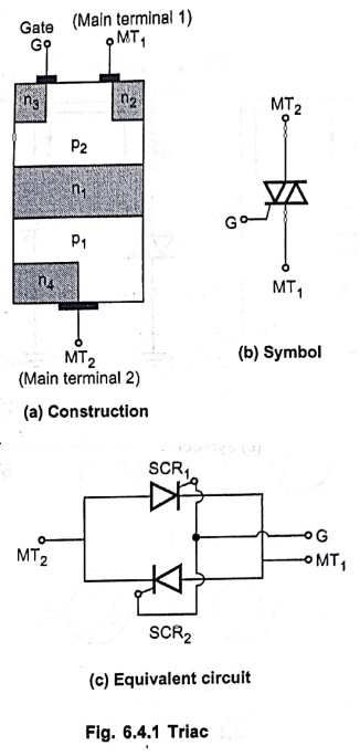
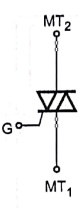
Fig. 6.4.1 (a) shows the basic construction of a triac. Fig. 6.4.1 (b) shows
the symbol of a triac. Fig. 6.4.1 (c) shows an equivalent circuit of a triac
which is antiparallel connection of the two SCRs.
•
As triac conducts both ways, conducts both ways, anode‒cathode terminology is
not used. The two main electrodes are called main terminals MT1 and
MT2 while common control terminal is called gate G. The gate
terminal is near MT1.
•
The triac can be turned ON by applying either a positive or negative voltage to
the gate G with respect to the main terminal MT1.
1. Working of Triac
• With gate open, either MT1 is positive with respect to MT2 or MT2 is positive with respect to MT1.
• Forward blocking
region: When gate is open and MT2 is
positive with respect to MT1 but the voltage is less than forward
breakover voltage then triac does not conduct. This region is called forward
blocking region. If this voltage is increased beyond breakover voltage, the
triac conducts in the forward direction.
•
Reverse blocking region: When
gate is open and MT2 is negative with respect to MT1 but
the voltage is less than breakover voltage then triac does not conduct. This
region is called reverse blocking region. But note that if this voltage is
increased beyond the breakover voltage, triac conducts in reverse direction.
•
In forward or reverse blocking, now if gate is made positive or negative with
respect to MT1 then also the triac conducts. This is the gate
control of triac and easy way of switching triac ON.
Key
Point: When MT2 is positive and MT1
is negative, triac is forward biased while when MT1 is positive and
MT2 is negative, triac is reverse biased.
•
Operating modes of triac: In
each biased state, gate can be positive or negative.
This
gives four different operating modes of triac.
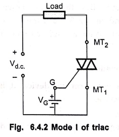
1. Mode I:
In this mode, triac is forward biased and gate is made positive with respect to
MT1. This is shown in Fig. 6.4.2. The terminal MT2 is
positive with respect to MT1 as triac is forward biased.
•
In this arrangement the breakdown occurs as a normal SCR.
•
The gate current is positive and the triac is said to be operating in in the
first quadrant of its V‒I characteristics. Hence this mode is also called It
mode of operation.
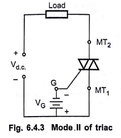
2. Mode II:
In this mode, triac is forward biased and gate is made negative with respect to
MT1. This is shown in Fig. 6.4.3. In this arrangement also the
breakdown occurs as a normal SCR.
•
The sensitivity to gate current is less in this mode. The gate current is
negative but triac still operates in first quadrant of its V‒I characterisitcs.
•
Due to negative gate, this mode is also called I mode of operation.
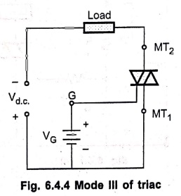
3. Mode III :
•
In this mode, triac is reverse biased i.e. MT1 is positive with
respect to MT2 and the gate is made positive as shown in Fig. 6.4.4.
•
The gate current initiates the conduction and due to regenerative action, the
triac is turned ON.
•
In this mode, direction of main SCR i.e. triac current reverses compared to
mode I and II and polarities of voltage between MT1 and MT2
are also reversed compared to mode I and II hence triac operates in third
quandrant of its V‒I characteristics. But due to positive gate, it is called
III+ mode.
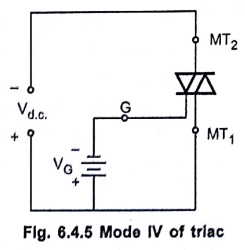
4. Mode IV:
In this mode, triac is reverse biased but gate is made negative as shown in
Fig. 6.4.5.
•
In this mode, gate current is negative and due to regenerative action, the
triac starts conducting.
•
Compared to III+ mode, in this mode only gate current direction is
reversed. Hence this mode is called III‒ mode.
•
The triac operation is in the third quadrant of its V‒I characteristics. In
this mode triac is more sensitive than III+ mode.
2. Characteristics of Triac
•
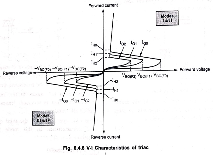
The triac has its characteristics in first quadrant and third quadrant.
•
The characteristics are exactly similar to that of SCR, but in both the
quadrants I and III and not like SCR only in first quadrant.
•
The mode I and II operations exist in first quadrant while mode III and IV
operations exist in the third quadrant.
•
The entire V‒I characteristics of triac are shown in Fig. 6.4.6.
3. Applications of Triac
•
The various applications of triac are,
1.
Static a.c. switching of applications.
2.
In a three position static switch.
3.
A.C. power flashers.
4.
Heater controllers or temperature controllers.
5.
As a triggering device for SCRs.
6.
Light dimmer circuits.
7.
The power control to the load.
8.
Proximity detector circuit.
9. A.C. voltage stabilizers.
•
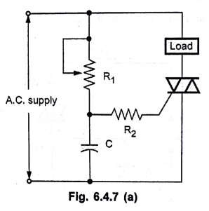
As triac is a bi‒directional device, it can easily be used to design variable
full wave rectifier, as shown in Fig. 6.4.7 (a).
•
In this circuit, resistance R1 and capacitance C shift the phase angle
of the gate signal. Because of this phase shift, the gate voltage lags the line
voltage by an angle between 0 and 90°.
•
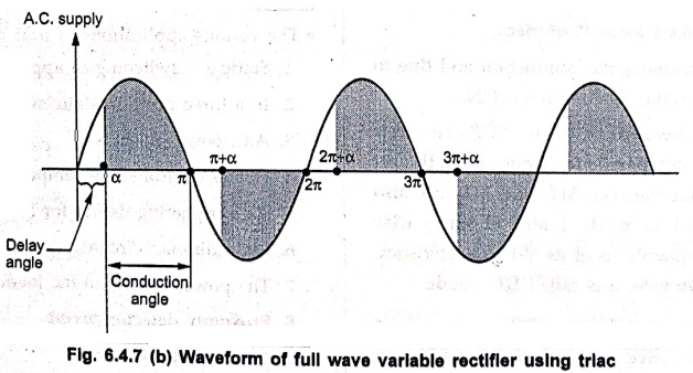
This voltage lag delays the firing of triac controlling the current through the
load.
•
As triac conducts in either direction, current in both positive and negative
half cycles can be controlled as shown in Fig. 6.4.7 (b). Power in shaded
portion only is available to the load.
4. Comparison of SCR and Triac
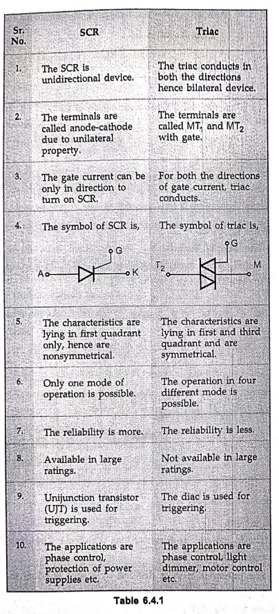
SCR
1.
The SCR is unidirectional device.
2.
The terminals are called anode‒cathode due to unilateral property.
3.
The gate current can be only in direction to turn on SCR.
4.
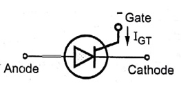
The symbol of SCR is,
5.
The characteristics are lying in first quadrant only, hence are nonsymmetrical.
6.
Only one mode of operation is possible.
7.
The reliability is more.
8.
Available in large ratings.
9.
Unijunction transistor (UJT) is used for triggering.
10.
The applications are phase control, protection of power supplies etc.
Triac
1.
The triac conducts in both the directions hence bilateral device.
2.
The terminals are called MT1 and MT2 with gate.
3.
For both the directions of gate current, triac conducts.
4. The symbol of triac is,
5.
The characteristics are lying in first and third quadrant and are symmetrical.
6.
The operation in four different mode is possible.
7.
The reliability is less.
8.
Not available in large ratings.
9.
The diac is used for triggering
10.
The applications are phase control, light dimmer, motor control etc.
5. Merits of Triac
1.
It conducts in both the directions hence power control in both the half cycles
is possible.
2.
Triac turns off when voltage is reversed, no external circuit is required to
turn off.
3.
Single gate controls the conduction in both the directions.
4.
Triacs with high voltage and current ratings are available.
5.
More economical than SCR.
6. Demerits of Triac
1.
Not suitable for d.c. power applications.
2.
Gate has no control over the conduction when triac is on.
3.
Triacs have very small switching frequencies.
4.
Power rating is less than SCR.
5.
The reliability is less than SCR.
6.
Low dv/dt and di/dt rating than SCR hence accidental turning on due to high
dv/dt of source voltage is possible.
Review Questions
1. What is triac? Explain its construction, symbol and
equivalent circuit.
2. Explain the working of triac.
3. Draw and explain the V‒I characteristics of triac. Explain
its operation.
4. List the applications of triac.
5. Explain any one application of triac in detail.
6. Compare SCR and triac.
7. List the merits of triac.
8. List the demerits of triac.
9. Draw the basic structure of TRIAC and its symbol.
Electron Devices: Chapter 6: Thyristors UJT and Optoelectronic Devices : Tag: electronics : Construction, Working Principle, Symbol, Equivalent circuit, VI characteristics, Comparison, Applications, Merits, Demerits - Triac
Electron Devices: Chapter 6: Thyristors UJT and Optoelectronic Devices
Under Subject

Electron Devices
EC25C01 2nd Semester ECE Dept | 2025 Regulation | 2nd Semester 2025 Regulation
Related Subjects

English Essentials II
EN25C02 2nd Semester | 2025 Regulation | 2nd Semester 2025 Regulation

Tamils and Technology தமிழர்களும் தொழில்நுட்பமும்
UC25H02 2nd Semester | 2025 Regulation | 2nd Semester 2025 Regulation

Linear Algebra
MA25C02 2nd Semester | 2025 Regulation
Electron Devices
EC25C01 2nd Semester ECE Dept | 2025 Regulation | 2nd Semester 2025 Regulation

Data Structures using CPlusPlus
CS25C05 2nd Semester ECE Dept | 2025 Regulation | 2nd Semester 2025 Regulation

Circuits and Network Analysis
EC25C02 2nd Semester ECE Dept | 2025 Regulation | 2nd Semester 2025 Regulation

Re-Engineering for Innovation
ME25C05 2nd Semester | 2025 Regulation | 2nd Semester 2025 Regulation

Engineering Drawing - Laboratory
ME25C01 2nd Semester | 2025 Regulation | 2nd Semester 2025 Regulation

Data Structures using CPlusPlus - Laboratory
CS25C05 2nd Semester ECE Dept | 2025 Regulation | 2nd Semester 2025 Regulation

Devices and Circuits Laboratory
EC25C03 2nd Semester ECE Dept | 2025 Regulation | 2nd Semester 2025 Regulation