Electron Devices: Chapter 6: Thyristors UJT and Optoelectronic Devices
Liquid Crystal Display (LCD)
Construction, Operation, Types, Characteristics, Applications, Comparison, Advantages, Disadvantages

Questions: 1. Explain construction and operation of LCD. 2. State the types of liquid crystals and explain their structures in brief. 3. Explain the construction and working principle of dynamic scattering LCD. 4. Explain the construction and working principle of field effect LCD. 5. State the advantages of LCD. 6. State the disadvantages of LCD. 7. Compare LED and LCD.
Liquid
Crystal Display (LCD)
•
The liquid crystals are one of the most fascinating material systems in nature,
having properties of liquids as well as of a solid crystal. The terms liquid
crystal refers to the fact that these compounds have a crystalline arrangement
of molecules, yet they flow like a liquid. Liquid crystal displays do not emit
or generate light, but rather alter externally generated illumination. Their
ability to modulate light when electrical signal is applied has made them very
useful in flat panel display technology.
•
A material in which the crystalline arrangement of molecules is disturbed when
electric field is applied, causing the changes its optical properties is called
liquid crystal material.
Types of Liquid Crystals
•
The crystal is made up of organic molecules which are rod like in shape with a
length of ‒20 °A ‒ 100 °A. The orientation of the rod like molecule defines the
"director" of the liquid crystal. The different arrangements of these
rod like molecules leads to three main categories of liquid crystals.
1.
Smectic 2. Nematic 3. Cholesteric.
1. Smectic
•
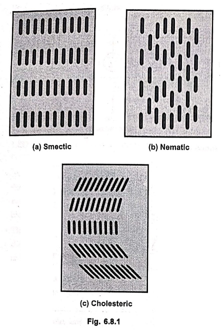
Fig. 6.8.1 (a) shows smectic structure of liquid crystals.
• In this structure the rod like molecules are arranged in layers, and within each layer there is orientational order over a long range. Thus in a given layer, the rods are all oriented in the same direction. Also, in the smectic liquid crystals the molecules of different layers are ordered as shown spil 99 in Fig. 6.8.1 (a).
•
Thus both orientation order and positional order is present in the smectic
crystals.
2. Nematic
•
Fig. 6.8.1 (b) shows nematic structure of liquid crystals. In the nematic
structure the positional order between layer of molecules is lost, but the
orientation order is maintained.
3. Cholesteric
•
Fig. 6.8.1 (c) shows cholesteric structure of liquid crystals. In these
crystals the rod like molecules in each layer are oriented in a different angle
within each layer. Orientation order is maintained in each layer. The cholesteric
liquid crystal is related to the nematic crystal, with the difference being the
twist of the molecules as one goes from one layer to another.
•
The optical activity of the crystal depends upon the orientation and the twist
of the molecules as one goes from one layer to another.
•
There are two types of liquid crystal displays (LCDs) according to the theory
of operation :
1.
Dynamic scattering LCD
2.
Field effect LCD.
i. Dynamic Scattering LCDs
•
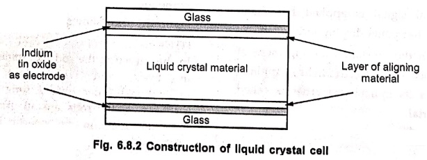
Fig. 6.8.2 shows the construction of a typical liquid crystal cell.
•
It consists of a layer of liquid crystal material sandwiched between glass
sheets with transparent metal film electrodes. Usually, an optically thin
(about 50 nm) layer of Indium Tin Oxide (ITO) on each surface acts as an
electrode to allow a voltage to be held across the cell. The aligning treatment
is then applied on the top of ITO.
•
When the cell is not activated, the liquid crystal is transparent.
• When it is activated, the molecular turbulence causes the light to be scattered in all directions so that the activated areas appear bright. This phenomenon is known as dynamic scattering.
•
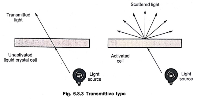
With both glass sheets transparent, the cell is known as a transmittive type
cell. When only one glass sheet is transparent and other has a reflective
coating, the cell is termed reflective type.
Transmittive Type Cell
•
When not activated, cell will simply transmit rear or edge lighting through the
cell in straight lines. In this condition the cell will not appear bright. When
the cell is activated, the incident light scatters and cell appears quite
bright. This is illustrated in Fig. 6.8.3.
Reflective Type Cell
•
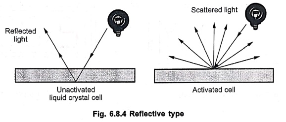
The reflective type cell operates from light incident on its front surface.
When it is not activated, light is reflected in the usual way from the mirror
surface, and the cell does not appear bright. When it is activated, the dynamic
scattering occurs and cell appears bright. This is illustrated in Fig. 6.8.4.
ii. Field Effect LCD
Fig.
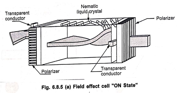
6.8.5 shows the field effect liquid crystal cell. It consists of two glass
plates, a liquid crystal fluid, polarizers and transparent conductors. The
liquid crystal fluid is sandwiched between two glass plates. Each glass plate
is associated with light polarizer. The light polarizers are placed at right
angle to each other. In the absence of electrical excitation, the light coming
through the front polarizer is rotated through 90° in the fluid and passed
through through the rear polarizer. It is then reflected to the viewer by the
back mirror as shown in Fig. 6.8.5 (a).
•
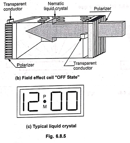
On the application of electrostatic field, the liquid crystal fluid molecules
get aligned and therefore light through the molecules is not rotated by 90° and
it is absorbed by the rear polarizer as shown in Fig. 6.8.5 (b).
•
This causes the appearance of dark digit on a light background as shown in Fig.
6.8.5 (c).
Advantages of LCDs
1.
Less power consumption.
2.
Low cost.
3.
Uniform brightness with good contrast.
4.
Low operating voltage and current.
Disadvantages of LCDs
1.
Poor reliability.
2.
Limited temperature range.
3.
Poor visibility in low ambient temperature.
4.
Slow speed.
5.
Requires an a.c. drive.
Applications
The
various applications of LCD are,
1.
7‒segment displays
2.
Calculators, pagers and Wrist‒watch
3.
Flat panel displays
4.
Alphanumeric displays
5.
Portable instruments
6.
Telephone sets
7.
For forming pixels on the screen of televisions, laptops and cameras.
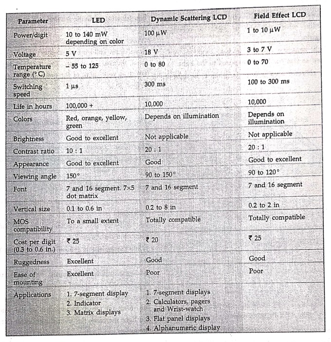
Comparison between LED and LCDs
Review Questions
1. Explain construction and operation of LCD.
2. State the types of liquid crystals and explain their
structures in brief.
3. Explain the construction and working principle of dynamic
scattering LCD.
4. Explain the construction and working principle of field
effect LCD.
5. State the advantages of LCD.
6. State the disadvantages of LCD.
7. Compare LED and LCD.
8. An indicator requires voltage to be displayed in seven
segment format. However, the power requirement for the display should be very
low. Choose a proper display device and justify your choice. Also indicate the
characteristics and operating principle of such a display device.
Electron Devices: Chapter 6: Thyristors UJT and Optoelectronic Devices : Tag: electronics : Construction, Operation, Types, Characteristics, Applications, Comparison, Advantages, Disadvantages - Liquid Crystal Display (LCD)
Electron Devices: Chapter 6: Thyristors UJT and Optoelectronic Devices
Under Subject

Electron Devices
EC25C01 2nd Semester ECE Dept | 2025 Regulation | 2nd Semester 2025 Regulation
Related Subjects

English Essentials II
EN25C02 2nd Semester | 2025 Regulation | 2nd Semester 2025 Regulation

Tamils and Technology தமிழர்களும் தொழில்நுட்பமும்
UC25H02 2nd Semester | 2025 Regulation | 2nd Semester 2025 Regulation

Linear Algebra
MA25C02 2nd Semester | 2025 Regulation
Electron Devices
EC25C01 2nd Semester ECE Dept | 2025 Regulation | 2nd Semester 2025 Regulation

Data Structures using CPlusPlus
CS25C05 2nd Semester ECE Dept | 2025 Regulation | 2nd Semester 2025 Regulation

Circuits and Network Analysis
EC25C02 2nd Semester ECE Dept | 2025 Regulation | 2nd Semester 2025 Regulation

Re-Engineering for Innovation
ME25C05 2nd Semester | 2025 Regulation | 2nd Semester 2025 Regulation

Engineering Drawing - Laboratory
ME25C01 2nd Semester | 2025 Regulation | 2nd Semester 2025 Regulation

Data Structures using CPlusPlus - Laboratory
CS25C05 2nd Semester ECE Dept | 2025 Regulation | 2nd Semester 2025 Regulation

Devices and Circuits Laboratory
EC25C03 2nd Semester ECE Dept | 2025 Regulation | 2nd Semester 2025 Regulation