Electron Devices: Chapter 6: Thyristors UJT and Optoelectronic Devices
Optocoupler or Optoisolator
Construction, Working Principle, Characteristics, Equivalent Circuit, Advantages, Applications

Questions: 1. Explain the construction and working of optocoupler. 2. Write a note on optocoupler. 3. Write a note on LED - phototransistor optocoupler. 4. State the characteristics of optocoupler. 5. State the advantages of optocoupler. 6. State the applications of optocouplers.
Optocoupler
or Optoisolator
•
A package which is a combination of light source like LED and a light detector
such as photodiode is called an optocoupler or optoisolator.
1. Construction and Working of Optocoupler
Fig.
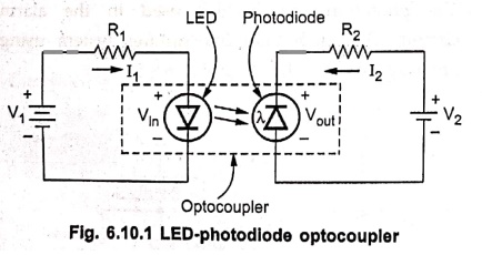
6.10.1 shows the basic construction of LED‒photodiode type of optocoupler.
•
The LED is forward biased using voltage V1 and series resistance R1.
The forward current of LED is I1. Thus LED emits the light.
•
The emitted light falls on a photodiode which is reverse biased using a voltage
V2. The reverse current I2 changes according to the light
absorped by the photodiode.
•
The output voltage is the difference between the voltage V2 and the
drop across the resistance R2.
Vout = V2‒I2R2
•
If the input voltage is changed, the amount of light emitted by LED changes.
This changes the reverse current of the photodiode. Hence the output voltage
changes.
•
The output voltage is optically coupled with the input voltage, though
electrically isolated. Thus the deviced couples input circuit to output circuit
optically hence called optocoupler or optoisolator.
•
The various types of optocouplers are,
1.
LED - LDR (Light Dependent Resistor) optocoupler
2.
LED ‒ photodiode optocoupler
3.
LED ‒ phototransistor optocoupler.
2. LED Phototransistor Optocoupler
•
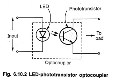
Fig. 6.10.2 shows LED ‒ phototransistor optocoupler.
•
The input voltage and a series resistance is used to forward bias the LED. Due
to forward current, LED emits the light. The light falls on the
phototransistor.
•
The phototransistor becomes ON and the resulting current drives the load.
•
Thus the input gets optically coupled to the output load providing electric
isolation.
•
This is very commonly used optocoupler as additional amplification of current
is not required.
3. Characteristics of Optocoupler
•
The various characteristics of optocoupler are,
1. Current Transfer
Ratio (CTR): It is the ratio of output collector
current (IC) to the input forward current (IF).
2. Isolation voltage
between input and output (Viso): This is
important as optocouplers are used to transmit signals from one circuit to
another which are having different potentials. It is specified in KVrms.
3. Response time:
It indicates how fast the optocoupler can change its state. It depends on
output phototransistor.
4. Common mode
rejection: Though optocouplers provide electric isolation, for
low frequency signal, a common noise can appear at the output due to stray
capacitance. The common mode rejection indicates the ability of the optocoupler
to reject such common mode signals. Its value must be high.
4. Advantages of Optocoupler
•
The various advantages of optocoupler are,
1.
Provides electric isolation between input and output.
2.
The response time is very small hence operation is fast.
3.
Capable of wideband signal transmission.
4.
Due to unidirectional signal transfer, the output does not loop back to the
input.
5.
Easy interfacing with logic devices.
6.
Compact and light weight.
7.
Changing load, does not affect the input.
8.
The problems such as noise, contact bounce etc. Mat are eliminated.
9.
No moving parts hence less maintenance.
5. Applications of Optocoupler
•
The various applications of optocouplers are,
1.
Mostly used for high voltage applications due to electric isolation.
2.
Interfacing the output of computer to external electric circuit.
3.
In driving the motors, relays, buzzers, alarms etc.
4.
In a.c. to d.c. converters used for d.c. motor speed control.
5.
In high power choppers and inverters.
Review
Questions
1. Explain the construction and working of optocoupler.
2. Write a note on optocoupler.
3. Write a note on LED - phototransistor optocoupler.
4. State the characteristics of optocoupler.
5. State the advantages of optocoupler.
6. State the applications of optocouplers.
Electron Devices: Chapter 6: Thyristors UJT and Optoelectronic Devices : Tag: electronics : Construction, Working Principle, Characteristics, Equivalent Circuit, Advantages, Applications - Optocoupler or Optoisolator
Electron Devices: Chapter 6: Thyristors UJT and Optoelectronic Devices
Under Subject

Electron Devices
EC25C01 2nd Semester ECE Dept | 2025 Regulation | 2nd Semester 2025 Regulation
Related Subjects

English Essentials II
EN25C02 2nd Semester | 2025 Regulation | 2nd Semester 2025 Regulation

Tamils and Technology தமிழர்களும் தொழில்நுட்பமும்
UC25H02 2nd Semester | 2025 Regulation | 2nd Semester 2025 Regulation

Linear Algebra
MA25C02 2nd Semester | 2025 Regulation
Electron Devices
EC25C01 2nd Semester ECE Dept | 2025 Regulation | 2nd Semester 2025 Regulation

Data Structures using CPlusPlus
CS25C05 2nd Semester ECE Dept | 2025 Regulation | 2nd Semester 2025 Regulation

Circuits and Network Analysis
EC25C02 2nd Semester ECE Dept | 2025 Regulation | 2nd Semester 2025 Regulation

Re-Engineering for Innovation
ME25C05 2nd Semester | 2025 Regulation | 2nd Semester 2025 Regulation

Engineering Drawing - Laboratory
ME25C01 2nd Semester | 2025 Regulation | 2nd Semester 2025 Regulation

Data Structures using CPlusPlus - Laboratory
CS25C05 2nd Semester ECE Dept | 2025 Regulation | 2nd Semester 2025 Regulation

Devices and Circuits Laboratory
EC25C03 2nd Semester ECE Dept | 2025 Regulation | 2nd Semester 2025 Regulation