Computer Organization and Architecture: Chapter 3: Processor Design
Microprogrammed Control
Processor Design
Questions: 1. What modification is required in the basic organization to support microprogram branching? 2. Explain the basic concept of microprogrammed control. 3. Describe the organization of microprogrammed control unit. 4. State the advantages and disadvantages of microprogrammed control. 5. Show the control sequences for execution of Add (R3), R1 and explain. 6. Explain microinstruction sequencing with next address field. 7. List out the advantages and limitations of a hardwired control unit. Explain the organization of a micro programmed control unit.
Microprogrammed
Control
•
Every instruction in a processor is implemented by a sequence of one or more
sets of concurrent microoperations. Each microoperation is associated with a
specific set of control lines which, when activated, causes that microoperation
to take place.
•
Since the number of instructions and control lines is often in the hundreds,
the complexity of hardwired control unit is very high. Thus, it is costly and
difficult to design.
•
Further more, the hardwired control unit is relatively inflexible because it is
difficult to change the design, if one wishes to correct design error or modify
the instruction set.
• Microprogramming
is a method of control unit design in which the control signal selection and
sequencing information is stored in a ROM or RAM called a Control Memory CM. The control signals to be activated at any time
are specified by a microinstruction,
which is fetched from CM in much similar way an instruction is fetched from
main memory.
•
Each microinstruction also explicitly or implicitly specifies the next
microinstruction to be used, thereby providing the necessary information for
sequencing.
•
A sequence of one or more microoperations designed to control specific
operation, such as addition, multiplication is called a microprogram. The microprograms for all instructions are stored in
the control memory.
•
The address where these microinstructions are stored in CM is generated by microprogram sequencer/microprogram controller. The microprogram sequencer
generates the address for microinstruction according to the instruction stored
in the IR.
•
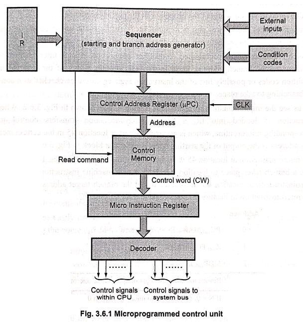
Fig. 3.6.1 shows the microprogrammed control unit. It consists of control
memory, control address register, micro instruction register and microprogram
sequencer.
•
The components of control unit work together as follows:
•
The control address register (µpc) holds the address of the next
microinstruction to be read. Every time a new instruction is loaded into the
IR, the output of the block labeled "starting address generator" is
loaded into the µpc.
■
When address is available in control address register, the sequencer issues
READ command to the control memory.
■
After issue of READ command, the word from the addressed location is read into
the microinstruction register.
■
The µpc is then automatically incremented by the clock, causing successive four
microinstructions to be read from the control memory.
■
The content of the micro instruction register generates control signals which
are delivered to various parts of the processor in the correct sequence.
•
Number of times the control unit is required to check the status of the
condition codes or external inputs to choose between alternative courses of
action.
•
In such situation, microprogrammed control use conditional branch
microinstructions. In additions to the branch address, these instructions
specify which of the external inputs, condition codes or possibly bits of the
instruction register should be checked as a condition for branching to take
place.
•
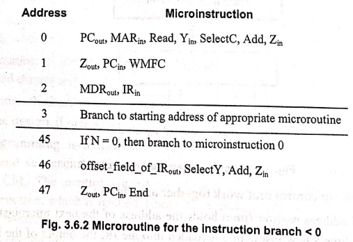
Let us see the implementation of instruction Branch < 0, as shown in Fig.
3.6.2. When this instruction is loaded into IR, a branch microinstruction
transfers control to the corresponding microroutine, which is assumed to start
at location 45 in the control memory. This address is the output of the starting
address generator block in Fig. 3.6.1.
•
The microinstruction at location 45 tests the N bit of the condition codes. If
this bit is equal to 0, a branch takes place to location 0 to fetch a new
machine instruction. Otherwise, the microinstruction at location 46 is executed
to put the branch target address into register Z. The microinstruction in
location 47 loads this address into the PC.
•
To support microprogram branching, the starting address and branch address generator
block loads a new address into the upc when a microinstruction instructs it to
do so.
•
To allow implementation of conditional branch, the external inputs, condition
codes and the contents of IR are given to the starting address and branch address
generator block.
•
Let us see how the µpc is used at different situations.
1.
When a new instruction is loaded into the IR, the µpc is loaded with the
starting address of the microroutine for that instruction.
2.
When a Branch microinstruction is encountered and the branch condition is
satisfied, the µpc is loaded with the branch address.
3.
When the end instruction is encountered, the µpc is loaded with the address of
the first Control Word (CW) in the microroutine for the instruction fetch
cycle, i.e. address 0.
4.
In any other situation, the µpc is incremented every time a new
microinstruction is fetched from the control memory.
Advantages of Microprogrammed Control
•
It simplifies the design of control unit. Thus it is both, cheaper and less
error prone to implement.
•
Control functions are implemented in software rather than hardware.
•
The design process is orderly and systematic.
•
More flexible, can be changed to accommodate new system specifications or to
correct the design errors quickly and cheaply.
•
Complex function such as floating point arithmetic can be realised efficiently.
•
The new or modified instruction set of CPU can be easily implemented by simply
rewriting or modifying the contents of control memory.
•
The fault can be easily diagnosed in the micro‒program control unit using
diagnostics tools by maintaining the contents of flags, registers and counters.
Disadvantages of Microprogrammed Control
•
A microprogrammed control unit is somewhat slower than the hardwired control
unit, because time is required to access the microinstructions from CM.
•
The flexibility is achieved at some extra hardware cost due to the control
memory and its access circuitry.
•
The design duration of micro‒program control unit is more than hardwired control
unit for lo smaller CPU.
•
Besides these disadvantages, the microprogramming is the dominant technique for
implementing control units.
Example: 1
Write a combined micro
routine that can implement that BGT (Branch if > 0), BPL (Branch if plus)
and BR (Branch Unconditionally) instructions. The branch conditions. for the
BGT and BPL instructions are Z + (N XOR V) = 0 and N = 0, respectively. What is
the total number of micro instructions required? How many micro instructions
are needed if a separate micro routine is used for each machine instruction?
Solution:
For
bus organisation, we write microroutine for the implementation of BGT (Branch
if > 0), BPL (Branch if plus) and BR (Branch unconditionally) instructions
as follows.
Combine Microroutine
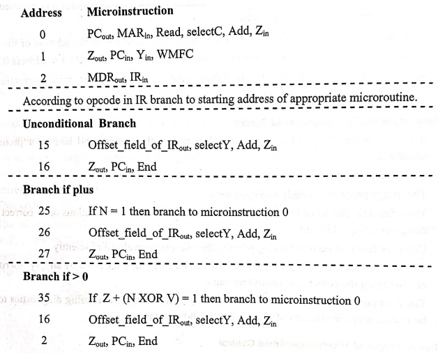
•
The first three microinstructions in the combine microroutine are used to fetch
the opcode. The total number of microinstructions required are 11. If a
separate microroutine is used for el each machine instruction 17
microinstructions are needed.
1. Microinstruction
•
A simple way to structure microinstructions is to assign one bit position to
each control signal required in the CPU. However, this scheme has one serious
drawback‒assigning individual bits to each control signal results in long
microinstructions, because the number of required signals is usually large.
Moreover, only a few bits are used in any given instruction. The solution of
this problem is to group the control signals.
1. Grouping of Control Signals
•
Grouping technique is used to reduce the number of bits in the
microinstruction. This technique is explained in the following section.
•
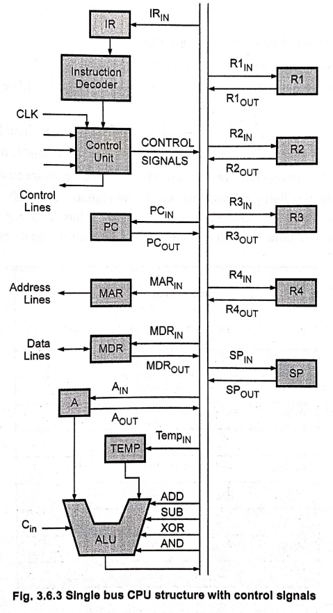
Let us consider single bus CPU having different control signals, as shown in
Fig. 3.6.3.
•
Gating signals: (IN and OUT
Signals).
•
Control signals: Read, write, clear
A, set carry in, continue operation, WMFC, end, etc.
•
ALU Signals: Add, sub, etc. There
are in all 39 signals and hence each microinstruction will have 39 bits. It is
not at all necessary to use all 39 bits for every microinstruction because by
using grouping of control signals we minimize number of bits for
microinstruction.
Ways to reduce number of bits in microinstruction
1.
Most signals are not needed simultaneously.
2.
Many signals are mutually exclusive e.g. Only one function of ALU can be
activated at a time.
3.
A source for data transfers must be unique which means that it should not be
possible to get the contents of two different registers on to the bus at the
same time.
4.
Read and write signals to the memory can't be activated simultaneously.
•
This suggests the possibility of grouping the control signals so that all the
signals that are mutually exclusive are placed in the same group. Thus a group
can specify one microinstruction at a time. So with this suggestions 39 control
signals can be grouped in 8 different groups.
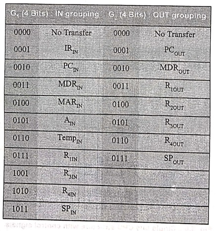
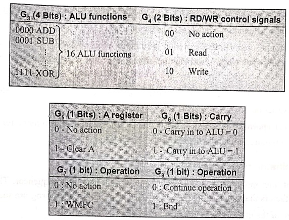
•
The total number of grouping bits are 18. Therefore, we minimized 39 bits
microinstruction to 18 bit microinstruction.
•
Grouping of control signals result in relatively small increase in the required
hardware as it becomes necessary to use decoding circuits to translate the bit
patterns of each group into actual control signals.
•
Since the number of bits required is less for microinstruction, less space is
required for microinstructions for the instruction.
2. Techniques of Grouping of Control Signals
•
The grouping of control signals can be done either by using technique called vertical organisation or by using
technique called horizontal
organisation.
•
Highly encoded scheme that use compact codes to specify only a small number of
control functions in each microinstruction are referred to as a vertical organisation.
•
On the other hand, the minimally encoded scheme, in which resources can be
controlled with a single instruction, is called a horizontal organisation.
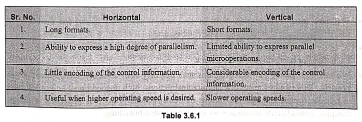
Table
3.6.1 shows the comparison between horizontal and vertical organisation.
•
The advantages and disadvantages of horizontal and vertical organisations can
be summarized as follows:
1.
The horizontal organisation approach is suitable when operating speed of
computer is a critical factor and where the machine structure allows parallel
usage of a number of resources.
2.
Vertical approach results in slower operations speed but less bits are required
in the microinstruction.
3.
In vertical approach the significant factor is the reduced requirement for the
parallel hardware required to handle the execution of microinstructions.
2. Microinstruction Sequencing
•
The task of microprogram sequencing is done by microprogram sequencer. There
are two important factors that must be considered while designing the
microprogram sequencer :
■
The size of the microinstruction and
■
The address generation time
•
The size of the microinstruction should be minimum so that the size of control
memory required to store microinstructions is also less. This reduces the cost
of control memory. With less address generation time, microinstructions can be
executed in less time, resulting better throughout.
•
During execution of a microprogram, the address of the next microinstruction to
be executed has three sources:
■
Determined by instruction register
■
Next sequential address
■
Branch
•
Out of these three address sources, first occurs only once per instruction
cycle. The second source is most commonly used. However, if we store separate
microinstructions for each machine instruction, there will be large number of
microinstructions. As a result, large space in CM is required to store these
microinstructions.
•
We know that, machine instructions involve several addressing modes and there
can be many instructions and addressing mode combinations.
•
A separate microinstructions for each of these combinations would produce
considerable duplication of common microinstructions.
•
We want to organize the microprograms such that they share as many
microinstructions as possible. This requires many branch microinstructions,
both unconditional and conditional to transfer control amongst the various
microinstructions. Thus it is important to design compact, time‒efficient
techniques for microinstruction branching.
•
Let us see how microinstructions can be shared using microinstruction
branching. Consider instruction ADD Rsrc, Rdst. The
instruction adds the source operand to the contents of register Rdst
and places the sum in Rdst, the destination register.
• Let us assume that the source operand can be specified in the following addressing modes: Indexed, autoincrement, autodecrement, register indirect and register direct. We now use this instruction in conjunction with the CPU structure shown in Fig. 3.6.4 to demonstrate a possible microprogrammed implementation.
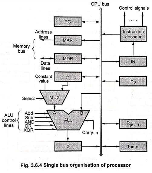
•
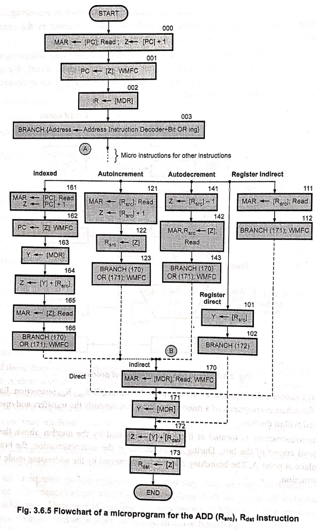
Fig. 3.6.5 shows a flowchart of a microprogram for the ADD Rsrc, Rdst
instruction. Each box in the flowchart corresponds to a microinstruction that
controls the transfers and operations indicated within the box.
•
The microinstruction is located at the address indicated by the number above
the upper right‒hand corner of the box. During the execution of the
microinstruction, the branching takes place at point A. The branching address
is determined by the addressing mode used in the instruction.
•
At point B, it is necessary to choose between actions required by direct and
indirect addressing modes. If the indirect mode is specified in the
instruction, then the microinstruction in location 170 is performed to fetch
the operand from the memory. If the direct mode is specified, this fetch must
be bypassed by branching immediately to location 171. The remaining
microoperations required to complete execution of instruction are same and
hence shared by the instructions having operand with different addressing
modes.
•
From the above discussion we can say that branching allows sharing of
microinstructions for different microprograms and it reduces the size of
control memory.
3. Techniques for Modification or Generation of Branch Addresses
Bit‒ORing
•
In this technique, the branch address is determined by ORing particular bit or
bits with the current address of the microinstruction.
•
For example, if the current address is 170 and the branch address is 172 then
the branch address can be generated by ORing 02 (bit 1), with the current
address.
Using condition variables
•
In this technique the condition variables are used to modify the contents of
the CM address register directly, thus eliminating whole or in part the need
for branch addresses in microinstructions.
•
For example, let the condition variable CY indicate occurrence of CY = 1 and no
carry when CY = 0. Suppose that we want to execute a SKIP_ON_CARRY
microinstruction. This can be done by logically connecting CY to the count
enable input of µpc at on appropriate point in the microinstruction cycle. This
allows the overflow condition to increment µpc an extra time, thus performing
the desired skip operation.
Wide‒branch addressing
•
Generating branch addresses becomes more difficult as the number of branches
increases. In such situations Programmable Logic Array can be used to generate
the required branch addresses. This simple and inexpensive way of generating branch
addresses is known as wide‒branch
addressing.
•
Here, the opcode of a machine instruction is translated into the starting
address of the corresponding micro‒routine. This is achieved by connecting the
opcode bits of the instruction register as inputs to the PLA, which acts as a
decoder. The output of the PLA is the address of the desired microroutine.
Example: 2
For a single bus
organisation of CPU, write a microprogram for instruction. Add (Rsrc)
+,R dst.
Solution:
Let
us examine the path needed for the flowchart in 3.6.5 to execute the
instruction Add(Rsrc)+, Rdst
In
this instruction the source operand is accessed in the autoincrement mode and
the Rsrc and Rast are general purpose registers in the
processor. We assume that the processor has 16 registers that can be used for
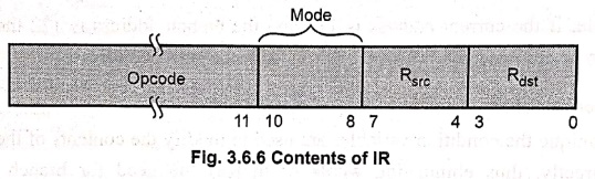
addressing purpose, each specified using a 4‒bit code. We also assume that the
instruction has a 3‒bit field, (bits 8‒10) used to specify the addressing mode
for the source operand, as shown in Fig. 3.6.6. Bit patterns 11,10,01 and 00
located in bits 10 and 9 denote the indexed, auto decrement, autoincrement and
register modes respectively. For each of these modes bit‒8 is used to specify
the indirect version. For example, 100 in the mode field specifies the direct
version of the autodecrement mode, whereas 101 specifies the indirect version.
As
a part of execution, first the opcode and mode fields are decoded to determine
that an Rsrc or Rdst register is involved. The decoded
output is then used to gate the contents of the Rsrc or Rdst
fields in the IR into a second decoder, which produces the gating signals for
the actual registers R0 to R15.
The
flowchart of a microprogram for the ADD Rsrc, Rdst
instruction in Fig. 3.6.5 is drawn by combining the microroutines for all
possible values of the mode field, resulting in a structure that requires many
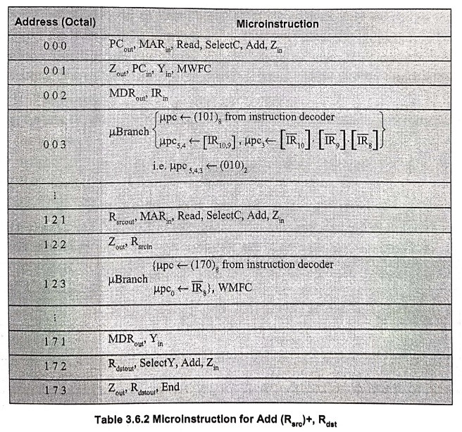
branch points. The instruction Add (Rsrc)+, Rdst requires
two branch microinstructions. In each branch microinstruction, the expression
in brackets indicates the branch address that is to be loaded into the upc and
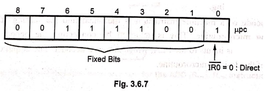
how this address is modified using the bit‒ORing scheme. For example, the
branch instruction at location 123 modifies the branch address 170 to 171 by
ORing the bit‒8 in the IR with bit pc0 to change the addressing mode from
indirect to direct, as shown in Fig. 3.6.7.
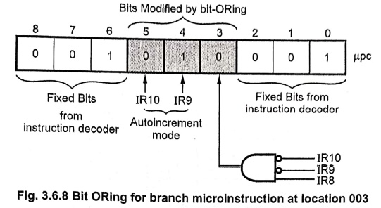
The
address for branch microinstruction at location 003 is generated as shown in
Fig. 3.6.8.
Table
3.6.2 gives the microinstruction sequence for the execution of Add (Rsrc)+,
Rdst instruction.
Example: 3
For a single bus
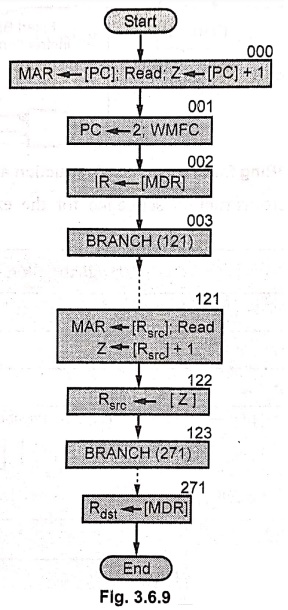
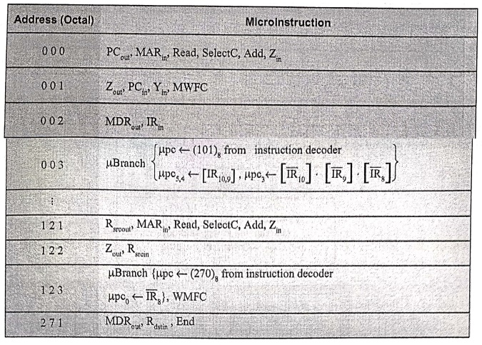
organisation of data paths inside the CPU, write a microprogram of micro‒instructions
and draw chart of a microprogram for the following instruction.MOV (Rsrc)+,
Rdst
Rast uses
direct and autoincrement addressing.
Solution: Flowchart
4. Microinstructions with Next Address Field
•
We have seen that in Fig. 3.6.5 requires several branch microinstructions.
These microinstructions perform no useful operation in the datapath; they are
needed only to determine the address of the next instruction. Thus they reduce
the operating speed of the processor. This situation can become significantly
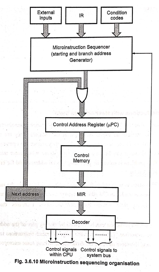
worse when other microroutines are considered. This problem is solved by
providing special address field for branch addresses as shown in Fig. 3.6.10.
•
Here, the branch address is stored in the special address field within the
microinstruction. The branch address is loaded in CM address register when a
branch condition is satisfied.
•
The special address field within the microinstruction increases the size of the
microinstruction.
• The size of the microinstruction can be reduced by storing part of the address (low order bits) in the microinstruction. This restricts the range of branch instructions to a small region of the CM and may therefore increase the difficulty of writing some microprograms.
5. Microinstruction Execution
•
A microprogrammed computer has two distinct levels of control.
i)
The instruction level and
ii)
The microinstruction level.
•
At the instruction level, the CPU continuously executes instruction cycles that
involve the following steps.
1.
The CPU fetches an instruction from main memory, whose address is stored in the
program counter PC.
2.
The opcode part of I is placed in an instruction register IR, the operation
specified by IR is then decoded and executed.
3.
PC is altered to point to the next instruction to be fetched from M.
•
A similar sequence of operations takes place at the lower microinstruction
level, where the control‒unit continuously executes microinstruction cycles as
follows:
1.
The addressing portion (microprogram sequencer) of the control‒unit fetches a
microinstruction MI from the control memory CM, whose address is stored in the
microprogram counter µpc.
2.
MI is loaded into the microinstruction register MIR and is decoded to produce the
required control signals.
3.
µpc is altered to point the next microinstruction to be fetched from CM.
•
A microinstruction cycle can be executed faster than an instruction cycle,
since microinstructions are stored within the CPU, whereas instructions must be
fetched from an external memory. Microinstructions also normally require less
decoding than instructions.
Review Questions
1. What modification
is required in the basic organization to support microprogram branching?
2. Explain the basic
concept of microprogrammed control.
3. Describe the
organization of microprogrammed control unit.
4. State the
advantages and disadvantages of microprogrammed control.
5. Show the control
sequences for execution of Add (R3), R1 and explain.
6. Explain
microinstruction sequencing with next address field.
7. List out the
advantages and limitations of a hardwired control unit. Explain the
organization of a micro programmed control unit.
Computer Organization and Architecture: Chapter 3: Processor Design : Tag: Computer : Processor Design - Microprogrammed Control
Computer Organization and Architecture: Chapter 3: Processor Design
Under Subject
Computer Organization and Architecture
CW25201 3rd Semester IT department. | 2025 Regulation | 3rd Semester 2025 Regulation
Related Subjects
Discrete Mathematics
MA25C14 3rd Semester CSE,IT,CY,AIDS departments. | 2025 Regulation | 3rd Semester 2025 Regulation
Data Structures
CS25C08 3rd Semester CSE,IT,CY,AIDS departments. | 2025 Regulation | 3rd Semester 2025 Regulation
Computer Organization and Architecture
CW25201 3rd Semester IT department. | 2025 Regulation | 3rd Semester 2025 Regulation
Object Oriented Programming
CS25C07 3rd Semester IT department. | 2025 Regulation | 3rd Semester 2025 Regulation
Web Technologies
IT25301 3rd Semester IT department. | 2025 Regulation | 3rd Semester 2025 Regulation
English Communication Skills Laboratory I
EN25C03 3rd Semester all department. | 2025 Regulation | 3rd Semester 2025 Regulation
Skill Development Course I
3rd Semester all department. | 2025 Regulation | 3rd Semester 2025 Regulation