Computer Programming C: UNIT I: Introduction to C
Flowchart
C Programming
A flowchart is a diagrammatic representation, that illustrates the sequence of operations to be performed to arrive at the solution.
FLOWCHART
1. INTRODUCTION
A
flowchart is a diagrammatic representation, that illustrates the sequence of
operations to be performed to arrive at the solution.
A
flowchart uses different shaped symbols to denote the different appropriate instructions
and these instructions can be written within the boxes using clear statements.
Then these boxes are connected by lines having arrow marks to indicate the flow
of operations, that is the exact sequence in which the instructions are to be
executed.
2. NEED FOR FLOWCHARTS
A
flowchart uses different shaped boxes to specify the several types of
instructions. The program logic is made very easy through the flowchart that
have standardised meaning.
Thus,
every programmer uses the same basic shapes, so others can easily read and
interpret the logic of the program. When the programmer looks at a flowchart,
it can be easily identified.
3. AIMS OF FLOWCHARTS
a)
Program preparation can be simplified using the flowcharts.
b)
Flowcharts are easier to understand at a glance, than the narrative description
of algorithm.
c)
Flowcharts are easy to analyse and compare various methods.
d)
Flowcharts assist in reviewing and debugging of a program.
e)
Flowcharts provide effective programming documentation.
f)
Using flowcharts, the method of solution adopted in a problem can be quickly
understood, instead of going through the tedious process of reading all the
program statements.
4. FLOWCHART SYMBOLS
For easy visual recognition, a standard conventions are used for drawing flowcharts. The flowchart symbols as given below are as per connection followed by International Standard Organization (ISO).
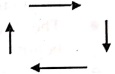
i. Flowlines:
These are the left to right or top to bottom lines connecting symbols. These
lines show the flow of control through the program.
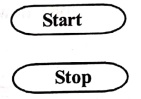
ii. Terminal symbol:
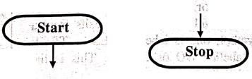
The oval shaped symbol always begins and ends the flowchart. It is the first
symbol and the last symbol of the program logic of flowchart. The start symbol
will have only one flow line but not entering flow line and a stop will have an
entering flow line but no exit.
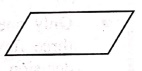
iii. Input/Output symbol:
The parallelogram is used for both Input (Read) and Output (Write), such that
this symbol is used to denote any function of an I/O device in the program.
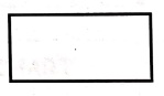
iv. Process symbol:
The rectangle symbol is used primarily for calculation and initialization of
memory locations. All the arithmetic operations, data movements, initialization
operations.
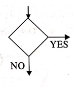
v. Decision symbol:
The diamond shaped symbol is used in a flowchart to indicate a point at which a
decision has to be made and a branch to one of two or more alternative point is
possible. There will be always two exits from a decision symbol, one is
labelled YES or TRUE and other labelled NO or FALSE. This is the only symbol
that can have two exits.
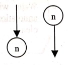
vi. Connectors:
A connector symbol is represented by a circle and a letter or digit placed in
the veros bons circle to specify the link. Whenever a complex flowchart is to
be drawn with a number of direction of flow lines is confusing or it is long as
over more than one page, in such a situation, the connector symbols are used to
connect the flowchart.
5. RULES FOR DRAWING A FLOWCHART
In
order to produce an efficient flowchart, the designer must follow the rules
given below.
•
The standard symbols should only be used.
•
The arrowheads in the flowchart represents the direction of flow of control in
the problem.
•
The usual direction of the flow of procedure is from top to bottom or left to
right.
•
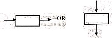
Only one flow line should come to a process symbol and only one flow line
should be out from a process symbol.
•
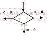
Only one flow line should enter a decision symbol, but two or three flow lines,
one for each possible answer, should leave the decision symbol.
•
Only one flow line is used in conjunction with terminal symbol.
•
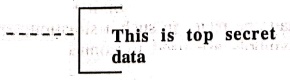
Write within standard symbols briefly. As necessary, use the annotation symbol
to describe data or computational steps more clearly.
•
The flow lines should not cross each other.
•
Be consistent in using names and variables in the flowchart.
•
Keep the flowchart as simple as possible.
•
Words in the flowchart symbols should be common statements and easy to
understand.
•
Chart the main line of logic, then incorporate all the details of logic.
•
If a new page is needed for flowcharting, then use connectors for better
representation.
•
Don't chart every detail or the flowchart will only be graphically represented.
Tips for Preparing Flowcharts
1.
Know your symbols.
2.
Create charts that flow from the top to the bottom of the page.
3.
Navigational lines should not intersect.
4.
Try to fit flowcharts on as few pages as possible.
5.
Use the simplest method when flowcharting.
6. BASIC DESIGN STRUCTURES IN FLOWCHART
By
using the basic flowchart symbols, we can design any program. Then we will be
combining them to design solutions to more complicated problems. In fact, the
ways in which we combine them have a lot to do with the clarity and
acceptability of our design. There are three generally accepted design
structures, such as sequence, selection and loop.
1. Sequence structure
It
is the simplest, because it is nothing more than a series of statements
performed one after another. It is a sequence because the flow sw always
continues in the same direction every time the structure is executed.
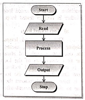
A
sequence may include a number of instructions, but each would be done in turn
in the same order.
2. Selection structure
Selection
structure uses a decision to ask some question. This structure includes the
decision and the operations to be performed in response to the decision. There
will be two exits from the decision, but both of these branches are still at
part of the selection structure, then both branches must re‒join a single flow
line to exit the structure. Using this selection structure, different steps may
be executed depending on the result of the decision test.
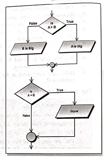
If
the selection only has an operation the true side, then it is called a one‒sided
selection, with this one‒sided structure the "null" side still must
have its exit from the decision box.
3. Loop structure
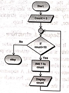
The
loop structure is used to execute a sequence of steps in a number of times or
until a particular condition is met. This structure will have a decision, one
or more additional symbols indicating the steps to be done within the loop and
a flow line that sends control to back to the beginning of the loop. Commonly
there are two loops available, one is top tested loop and another is bottom
tested loop.
a)
Top tested loop
The
top tested loops are leading decision loops, means that the decision is
evaluated the first statements of the loop. If it is true, the control follows
the flow lines that go into the loop. If it is false, control follows the flow
line to the first statement after the loop.
b)
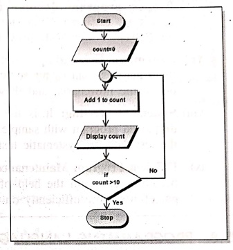
Bottom tested loop
This
loop is a trailing decision loop, which means that the decision is always at
the last statement of the loop. The body of the loop will be executed once before
control even gets to the loop test. In this loop, if the condition is false,
control follows the flow line back to the loop. If the test is true, control
follows the branch from the decision box that exits the loop structure.
7. ADVANTAGES OF FLOWCHARTS
The
use of flowcharts has several advantages which are given below:
i) To understand logic clearly:
Before coding the program, the programmer must be known about the logic of the
program. To make 6b or logic easier the programmer has to follow the task that
provides pictorial to representation. If programmer has a clear idea about the
logic, then only they will produce good programming.
ii) Better communication:
The flowcharts are better for communication, because "a picture is worth
thousand words." It is very easy for the programmer to explain the logic
of the program through the flowchart.
iii) Effective Analysis:
The flowcharts are very well suited to analyse the problem and can be broken
down into parts for study and further analysis of the system.
iv) Effective synthesis:
A team of designers or programmers are associated with the design of complex
system. Each designer or programmer is responsible for designing a part of the
entire system. So initially each designer or programmer draws a flowchart for
their part, then all the flowcharts from all the designers or programmers can
be placed together to visualize the overall system.
v) Effective coding:
After designing the flowchart, it is very easy to write programs, because
flowchart is the road map for the programmers.
vi) Proper program documentation:
The documentation involves collecting, organizing and storing a complete record
of program i.e., the flowcharts obviously provide the documentation support.
vii) Systematic Debugging:
After taking full care in program design, there may be chances for some errors.
Such errors can easily be found out in the flowcharts, and these can be
eliminated easily.
viii) Systematic Testing:
It is the process of executing the designed and developed program with sample
data. A flowchart is helpful in designing the test data for systematic testing
of programs.
ix) Efficient Program Maintenance:
The maintenance of operating program becomes easy with the help of flowchart.
It helps the programmer to put efforts more efficiently on that part.
8. PROGRAMMING LANGUAGES
Programming
languages are languages used to communicate with computers to create software,
websites, applications, and other technology. They allow people to write
instructions for computers to follow and create the technology we use every
day. Programming languages are essential in technology because they enable us
to automate tasks, make calculations, and process large amounts of data quickly
and efficiently.
Tabs
There are several programming languages that use paradigms, but to do this,
they need to follow a strategy or methodology. Below is an overview of
programming languages and their paradigm methodology.han the
• Imperative:
Programming with an explicit sequence of commands.
• Declarative:
Programming by specifying the result a user wants, instead of how to get it.
• Structured:
Programming with clean control structures.
• Procedural:
Imperative programming with procedure calls.
•
Functional: Programming with function calls that avoid any global state.
• Object‒Oriented:
Programming by defining objects that send messages to each other.
• Logic:
Programming by specifying a set of facts and rules.
• Constraint:
Programming by specifying a set of constraints.
• Reflective:
Programming by manipulating the program elements.
Computer Programming C: UNIT I: Introduction to C : Tag: Computer Science : C Programming - Flowchart
Computer Programming C: UNIT I: Introduction to C
Under Subject
Computer Programming C
CS25C01 1st Semester | 2025 Regulation | 1st Semester 2025 Regulation
Related Subjects

English Essentials I
EN25C01 1st Semester | 2025 Regulation | 1st Semester 2025 Regulation

தமிழர் மரபு - Heritage of Tamils
UC25H01 1st Semester | 2025 Regulation | 1st Semester 2025 Regulation

Applied Calculus
MA25C01 Maths 1 M1 - 1st Semester | 2025 Regulation | 1st Semester 2025 Regulation

Applied Physics I
PH25C01 1st Semester | 2025 Regulation | 1st Semester 2025 Regulation

Applied Chemistry I
CY25C01 1st Semester | 2025 Regulation | 1st Semester 2025 Regulation
Makerspace
ME25C04 1st Semester | 2025 Regulation | 1st Semester 2025 Regulation
Computer Programming C
CS25C01 1st Semester | 2025 Regulation | 1st Semester 2025 Regulation
Computer Programming Python
CS25C02 1st Semester | 2025 Regulation | 1st Semester 2025 Regulation
Fundamentals of Electrical and Electronics Engineering
EE25C03 1st Semester EEE Depart | 2025 Regulation | 1st Semester 2025 Regulation

Introduction to Mechanical Engineering
ME25C03 1st Semester Mechanical Dept | 2025 Regulation | 1st Semester 2025 Regulation

Introduction to Civil Engineering
CE25C01 1st Semester Civil, Agri Departments | 2025 Regulation | 1st Semester 2025 Regulation
Essentials of Computing
CS25C03 1st Semester - AIDS, CSE, CSE(CY), IT Department | 2025 Regulation | 1st Semester 2025 Regulation

Applied Physics I Laboratory
PH25C01 1st Semester practical Laboratory Manual | 2025 Regulation | 1st Semester Laboratory 2025 Regulation

Applied Chemistry I Laboratory
CY25C01 1st Semester practical Laboratory Manual | 2025 Regulation | 1st Semester Laboratory 2025 Regulation

Computer Programming C Laboratory
CS25C01 1st Semester EEE, ECE, CSE, CSE(CY), AIDS, IT practical Laboratory Manual | 2025 Regulation | 1st Semester Laboratory 2025 Regulation

Computer Programming Python Laboratory
CS25C02 1st Semester practical Laboratory Manual | 2025 Regulation | 1st Semester Laboratory 2025 Regulation
Engineering Drawing
ME25C01 EEE, Mech, Agri, EEE Depts | 2025 Regulation | 2nd Semester 2025 Regulation

Basic Electronics and Electrical Engineering
EE25C04 1st Semester ECE Dept | 2025 Regulation | 1st Semester 2025 Regulation
Essentials of Computing - Laboratory
CS25C03 1st Semester AIDS, CSE, CSE(CY), IT Depts | practical Laboratory Manual | 2025 Regulation | 1st Semester 2025 Regulation